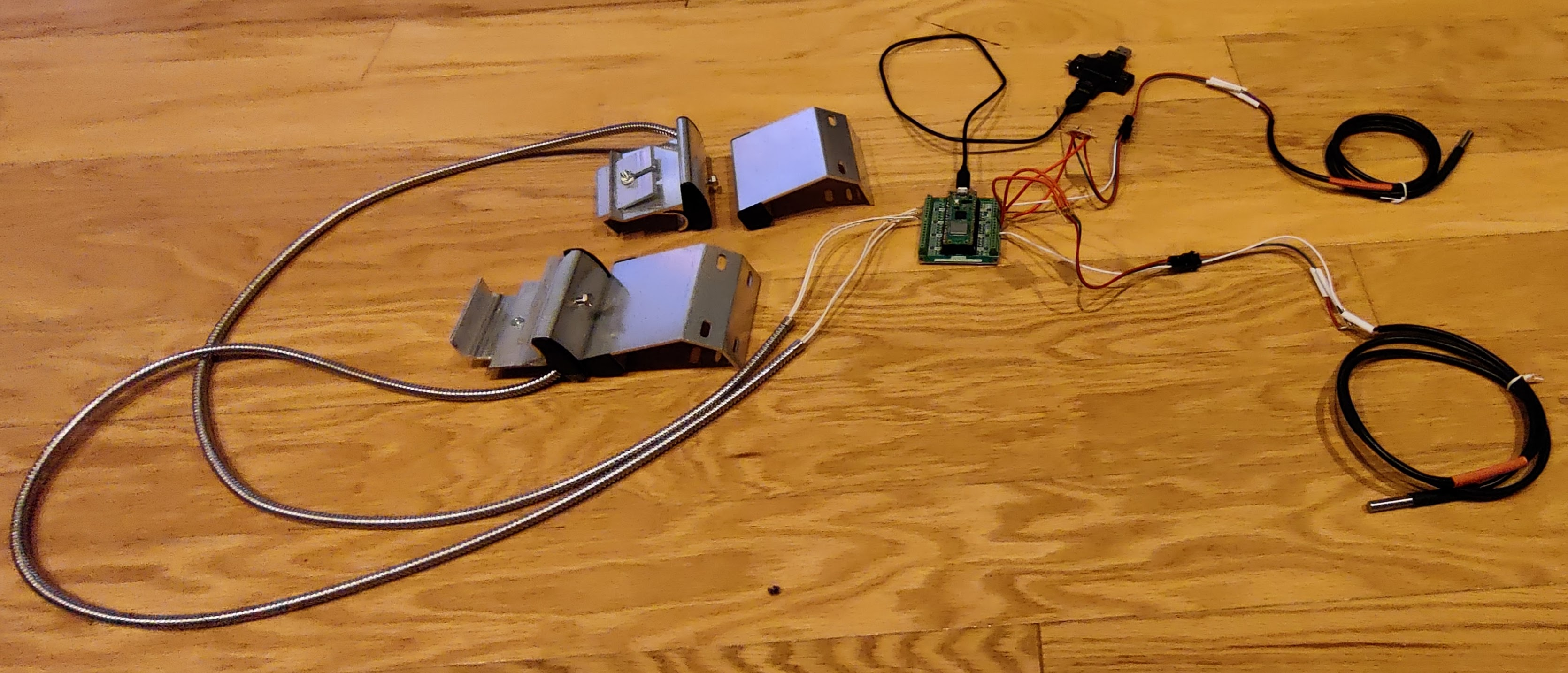
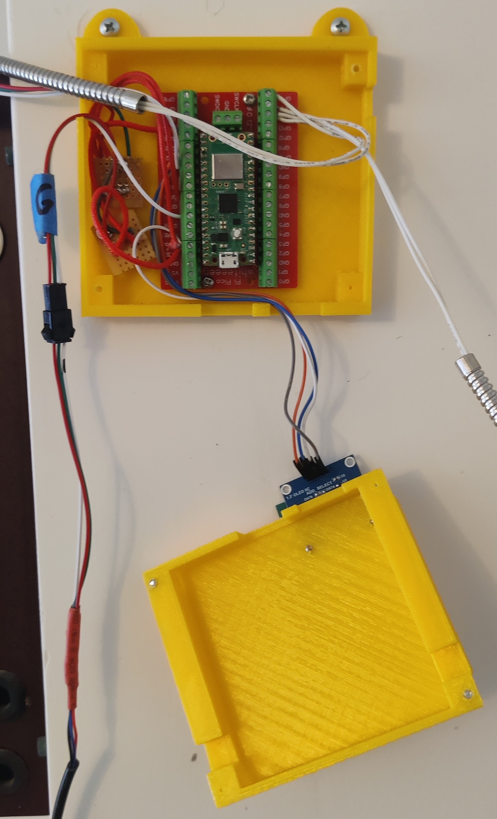
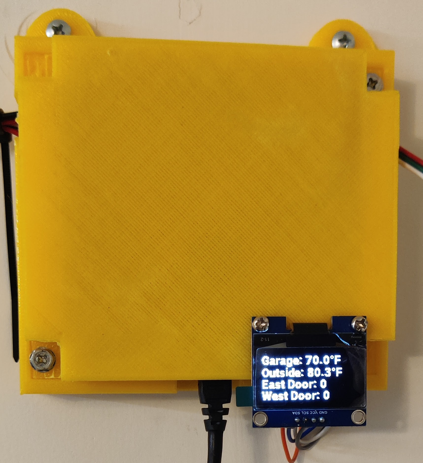
This is an adaptation of Jeff Geerling’s garage door sensor project. My adaptation adds two temperature sensors and a display.
Code
---
esphome:
  name: garage-door-temp-display-pico

rp2040:
  board: rpipicow
  framework:
    # Required until https://github.com/platformio/platform-raspberrypi/pull/36 is merged
    platform_version: https://github.com/maxgerhardt/platform-raspberrypi.git

wifi:
  ssid: !secret wifi_ssid
  password: !secret wifi_password
  fast_connect: true

api:
  encryption:
   key: "xxxxxxxxxxxxxxxxxxxxxxxxxxxxxx"

logger:
  level: DEBUG

output:
  # Built-in LED
  - platform: gpio
    pin:
      number: 32  # 25 for Pico (non-W)
      mode: output
    id: LED

binary_sensor:
  # East Garage Door
  - platform: gpio
    pin:
      number: 14
      mode:
        input: true
        pullup: true
        output: false
        open_drain: false
        pulldown: false
      inverted: false
    name: East Garage Door
    id: east_garage_door
    device_class: garage_door
    filters:
      - delayed_on: 10ms
    disabled_by_default: false
    publish_initial_state: true
    on_state:
      then:
        - if:
            condition:
              or:
                - binary_sensor.is_on: east_garage_door
                - binary_sensor.is_on: west_garage_door
            then:
              - output.turn_on: LED
            else:
              - output.turn_off: LED

  # West Garage Door
  - platform: gpio
    pin:
      number: 15
      mode:
        input: true
        pullup: true
        output: false
        open_drain: false
        pulldown: false
      inverted: false
    name: West Garage Door
    id: west_garage_door
    device_class: garage_door
    filters:
      - delayed_on: 10ms
    disabled_by_default: false
    publish_initial_state: true
    on_state:
      then:
        - if:
            condition:
              or:
                - binary_sensor.is_on: east_garage_door
                - binary_sensor.is_on: west_garage_door
            then:
              - output.turn_on: LED
            else:
              - output.turn_off: LED


# temperature
# Example configuration entry
dallas:
  - id: garage_temp_bus
    pin: GPIO18
  - id: outside_temp_bus
    pin: GPIO26

# Individual sensors
sensor:
  - platform: dallas
    address: 0x0000000000000000
    name: "Garage Temperature"
    dallas_id: garage_temp_bus
    id: garage_temp
  - platform: dallas
    address: 0x1111111111111111
    name: "Outside Temperature"
    dallas_id: outside_temp_bus
    id: outside_temp

font:
  - file: "fonts/Roboto-Black.ttf"
    id: roboto
    size: 15
i2c:
  sda: GPIO20
  scl: GPIO21

display:
  - platform: ssd1306_i2c
    model: "SH1106 128x64"
    rotation: 180
      #    reset_pin: 0
    address: 0x3C
    lambda: |-
      if (id(garage_temp).has_state()) {
        it.printf(0, 0, id(roboto),"Garage: %.1f°F", id(garage_temp).state*9/5+32);
      }
      if (id(outside_temp).has_state()) {
        it.printf(0, 16, id(roboto),"Outside: %.1f°F", id(outside_temp).state*9/5+32);
      }
      it.printf(0, 31, id(roboto), "East Door: %s", id(east_garage_door).state);
      it.printf(0, 46, id(roboto), "West Door: %s", id(west_garage_door).state);
Install Esphome
Install the following python packages
pip3 install wheel
pip3 install esphome
Flash Procedure
mkdir pico-pi

# Create the yaml file name and insert the code
vim garage-door-temperature-display.yml


# Compile the code
esphome run garage-door-temperature-display.yml --device /Volumes/RPI-RP2

cd ~/pico-pi/.esphome/build/garage-door-temperature-display.yml/.pioenvs/rpi-pico/

# Plugin the pico while press the flash button
# Run 'mount | grep RP' command to find the mount point

# flash the code on to the pico
cp firmware.uf2 /media/<user>/RPI-RP2
 `
`